Tuesday, April 19, 2016
A starless Melotte 15 in IC 1805
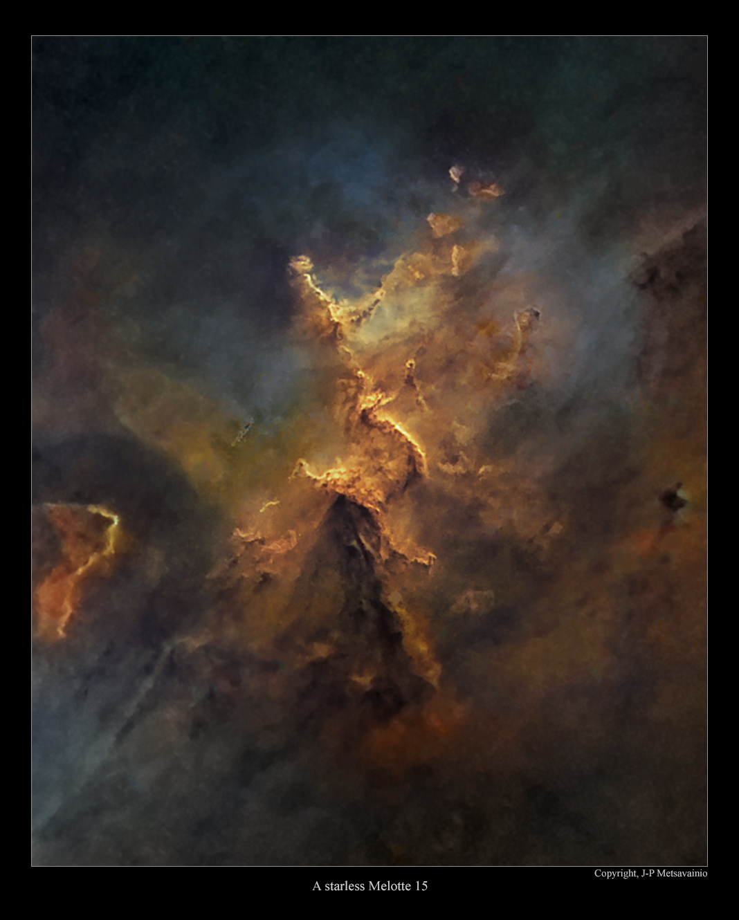
Now and then I publish experimental starless versions of my photos. They have a special eerie feel in them but they also reveal more details in the actual nebula.
Melotte 15 with no stars
Please, click for a large image
Blog post about IC 1805 and the Melotte 15 with all the stars
http://astroanarchy.blogspot.fi/2015/04/my-last-imaging-project-for-this-winter.html

Monday, April 18, 2016
Supernova remnant Sharpless 224 in stereo, an experimental 3D-study
Images are for two different viewing methods, the first set of images is for the Parallel Vision method and the second set for the Cross Vision method. Viewing instructions can be seen HERE.
NOTE! This is a personal vision about forms and shapes, based on some scientific facts, deduction and an artistic impression. A short explanation, about the method used for the 3D conversion of my astrophoto, at the end of this post.
Sh2-224 as a freeview stereo pairs
For a parallel viewing method (Eyes parallel to each other)

Original 2D-image and technical details can be seen HERE.
For a cross vision viewing method (Eyes crossed)
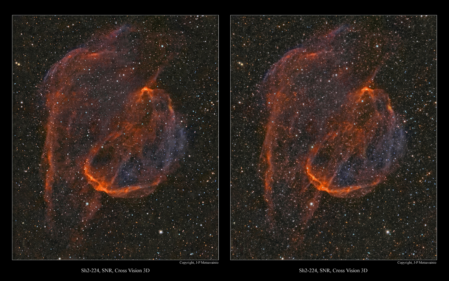
Original 2D-image and technical details can be seen HERE.
HOW?
All the original 2D-images are imaged by me, if not otherwise stated.
Due the huge distances, no real parallax can be imaged for a volumetric information.
I have developed a method to turn any 2D-astronomical image to a various 3D-formats. The result is always an approximation of the reality, based on some known scientific facts, deduction and an artistic impression.
What are the known facts?
By using a scientifically estimated distance of the object, I can organize right amount of stars front and behind the object. (as then we know the absolute position of the object at our Milky-way)
Stars are divided to groups by apparent brightness, that can be used as a draft distance indicator, brighter the closer. There is usually a known star cluster or a star(s) coursing the ionization and they can be placed in right relative position to the nebula itself .
Generally emission nebulae are not lit by the starlight directly but radiation from stars ionizing gases in the nebula. Hence the nebula itself is emitting its own light, at wavelength typical to each element. Due to that, and the thickness of the nebula can be estimated by its brightness, thicker = brighter. Nebulae are also more or less transparent, so we can see "both sides" at the same time.
Many other relative distances can be figured out just carefully studying the image, like dark nebulae must be front of bright ones. The local stellar wind, radiation pressure, from the star cluster, shapes the nebula, For that reason, pillar like formations must point to a cluster. ( Look previous image, above this text.) Same radiation pressure usually forms kind of cavitation, at the nebulosa, around the star cluster, by blowing away all the gas around the source of stellar wind. The ionized oxygen, O-III, emits blueish light, it requires lots of energy to ionize. Due to that, the blue glowing area locates usually near the source of ionization, at the heart of the nebula. This and many other small indicators can be found by carefully studying the image itself.
Using the known data, I can build a kind of skeleton model of the nebula. Then the artistic part is mixed to a scientific part, rest is very much like a sculpting.
Saturday, April 16, 2016
An experimental 3D-study of the NGC 1499, the California Nebula
Images are for two different viewing methods, the first set of images is for the Parallel Vision method and the second set for the Cross Vision method. Viewing instructions can be seen HERE.
NOTE! This is a personal vision about forms and shapes, based on some scientific facts, deduction and an artistic impression. A short explanation, about the method used for the 3D conversion of my astrophoto, at the end of this post.
NGC 1499 as a freeview stereo pairs
For a parallel viewing method (Eyes parallel to each other)

Original 2D-image and technical details can be seen HERE.
For a cross vision viewing method (Eyes crossed)
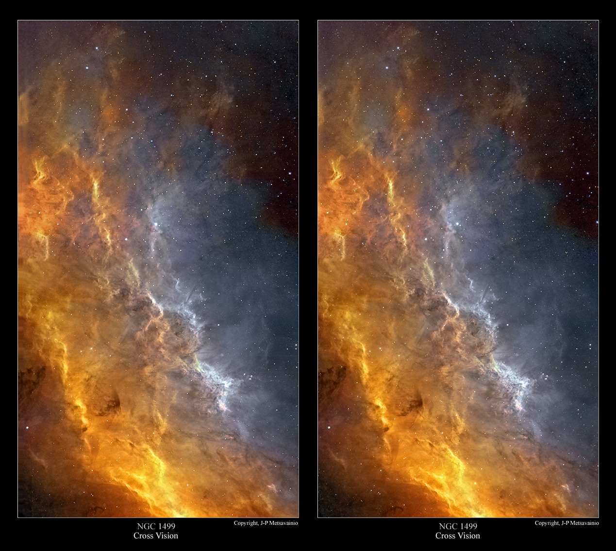
Original 2D-image and technical details can be seen HERE.
HOW?
I have been asked many times, how my 3D-images are done, so here it goes!
All the original 2D-images are imaged by me, if not otherwise stated.
Due the huge distances, no real parallax can be imaged for a volumetric information.
I have developed a method to turn any 2D-astronomical image to a various 3D-formats. The result is always an approximation of the reality, based on some known scientific facts, deduction and an artistic impression.
What are the known facts?
By using a scientifically estimated distance of the object, I can organize right amount of stars front and behind the object. (as then we know the absolute position of the object at our Milky-way)
Stars are divided to groups by apparent brightness, that can be used as a draft distance indicator, brighter the closer. There is usually a known star cluster or a star(s) coursing the ionization and they can be placed in right relative position to the nebula itself .
Generally emission nebulae are not lit by the starlight directly but radiation from stars ionizing gases in the nebula. Hence the nebula itself is emitting its own light, at wavelength typical to each element. Due to that, and the thickness of the nebula can be estimated by its brightness, thicker = brighter. Nebulae are also more or less transparent, so we can see "both sides" at the same time.
Many other relative distances can be figured out just carefully studying the image, like dark nebulae must be front of bright ones. The local stellar wind, radiation pressure, from the star cluster, shapes the nebula, For that reason, pillar like formations must point to a cluster. ( Look previous image, above this text.) Same radiation pressure usually forms kind of cavitation, at the nebulosa, around the star cluster, by blowing away all the gas around the source of stellar wind. The ionized oxygen, O-III, emits blueish light, it requires lots of energy to ionize. Due to that, the blue glowing area locates usually near the source of ionization, at the heart of the nebula. This and many other small indicators can be found by carefully studying the image itself.
Using the known data, I can build a kind of skeleton model of the nebula. Then the artistic part is mixed to a scientific part, rest is very much like a sculpting.
WHY?
Firstly, they are great fun to do. Secondly, just because I can.
Many times images of nebulae looks like paintings on the canvas. I like to show a real nature of those distant objects as a three dimensional shapes floating in a three dimensional volume. This is a great way to show, how I personally see astronomical targets as a 3D-forms inside my head.
3D-experiments seems to increase a public interest to a subject, as you might have noticed.
I have studied my astronomical images much deeper, than ever without 3D-modeling.
3D-studies has really added a new dimension to my work as an astronomical photographer. (pun intended)
Wednesday, April 13, 2016
Sharpless-114, the Flying Dragon Nebula, reprocessed data
Originally I published this photo of Sh2-114 at 8. November 2015. I did some reprocessing, especially to the mapped color version.
Also I found another photo of this emission area taken by the National Optical Astronomy Observatory and its four meter telescope. It was nice to notice, that my photo and processing with only 0.28 meter telescope could reveal a good level of details out of this dim target, if compared to a photo by Mayall 4-meter telescope at Kitt Peak National Observatory.
Sharpless-114, the Flying Dragon Nebula
Click for a large image
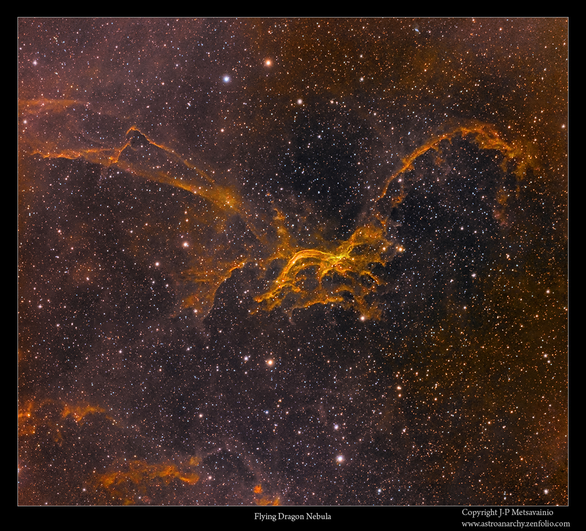
Image in mapped colors from the light emitted by the ionized elements.
Red=Sulfur, Green=Hydrogen and Blue=Oxygen.
Kitt Peak 4-meter telescope vs. Astro Anarchy 0.28-meter telescope
Click for a large image
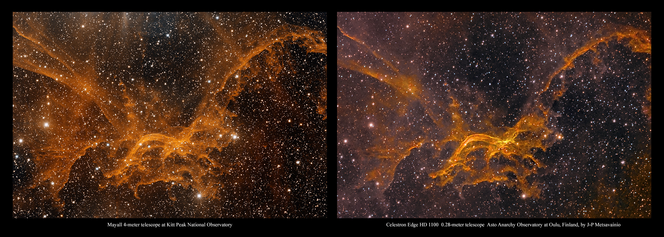
A photo by 4-meter telescope of NOAO compared to my photo of Sh2-114 with a Celestron Edge HD 11 inch telescope. Both images are in mapped colors from the light emitted by the ionized elements.
Photos are cropped,scaled and rotated to match the data.
Image in visual spectrum
Click for a large image
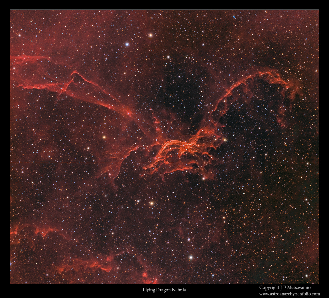
Natural color composition from the emission of ionized elements.
INFO
Sh2-114 is a complex and unusual HII emission nebula. Its complex, wispy structure is likely the result of winds from hot, massive stars interacting with the magnetic fields in the interstellar medium. But very little is known about it. (Source, https://www.noao.edu/image_gallery/html/im1112.html)
There is a planetary nebula at the same field of view, Lan 384 (Kn 26)
Using existing digital sky surveys, Jacoby et al. (2010) presented Kn 26, a bipolar PN candidate known for a long time as the emission line source Lan 384. Here we present high spatial-resolution optical and near-IR narrow-band images of this nebula, high-dispersion long-slit echelle spectra, and low-resolution spectroscopy. The new data confirm the PN nature of Kn 26 and reveal features typical of bipolar PNe: butterfly morphology, H2 emission, and nitrogen enrichment. A detailed analysis of the morphology and kinematics, however, suggests the possible presence of two pairs of bipolar lobes that would make Kn 26 a new member of the class of quadrupolar PN. (Source, http://www.iac.es/congreso/iaus283/pages/meeting/view-abstract.php?aid=138)
Lan 384 closeup

This is a closeup from top right third of my photo.
Info from Simbad database, http://simbad.u-strasbg.fr/simbad/sim-id?Ident=Lan+384
Some latest info confirms this a s bipolar planetary nebula, http://www.iac.es/congreso/iaus283/pages/meeting/view-abstract.php?aid=138
Technical details
Processing work flow
Image acquisition, MaxiDL v5.07.
Stacked and calibrated in CCDStack2.
Deconvolution with a CCDStack2 Positive Constraint, 21 iterations, added at 25% weight
Color combine in PS CS3
Levels and curves in PS CS3.
Imaging optics
Celestron Edge HD 1100 @ f7 with 0,7 focal reducer for Edge HD 1100 telescope
Mount
10-micron 1000
Cameras and filters
Imaging camera Apogee Alta U16 and Apogee seven slot filter wheel
Guider camera, Lodestar x2 and SXV-AOL
Astrodon filter, 5nm H-alpha
Astrodon filter, 3nm O-III
Astrodon filter, 3nm S-II
Exposure times
H-alpha, 9x 1200s = 3h
O-III, 3 x 1200s binned = 1h
S-II, 3 x 1200s binned = 1h
Total 5h
A single uncropped, calibrated and stretched 20 min. H-alpha frame as it comes from the camera

Subscribe to:
Posts (Atom)


