Saturday, February 21, 2015
A two frame mosaic of the Veil Nebula in light of ionized oxygen only
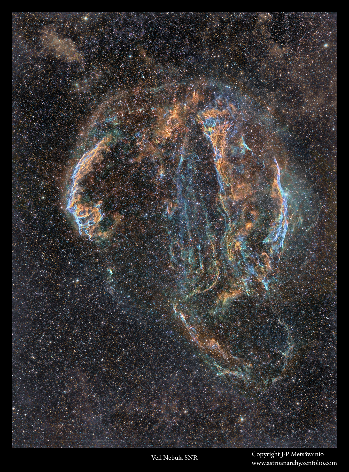
I started an imaging project of the Veil Nebula at 05. of November 2014. After this short period of time, clouds rolled in for about three months and my project was interrupted. Now the Veil nebula is too low in the horizon and I need to wait to next Autumn to finalize this image. In two nights, I shot 36 frames of O-III emission, 20 min. each, total 12 hours. There are two panels stitched together, exposure time for each panel is 6h.
Pickering's Triangle in O-III light alone
Part of the Veil nebula supernova remnant in Cygnus

A closeup
Click for a large photo

A horizontal version
(Click for a large photo, 1850x1000 pixels)

An older wide field photo of the veil nebula in O-III light
image is colorized

Pickering's Triangle in mapped colors
An older photo from 2012

are from emission of sulfur and hydrogen, bluish hues are from ionized oxygen.
Original blog post with the technical details can be seen HERE
An older wide field image of the Veil nebula
Image is in mapped colors from emission of ionized elements, H-a, S-II and O-III
Technical details
Processing work flow
Image acquisition, MaxiDL v5.07.
Stacked and calibrated in CCDStack2.
Color combine in PS CS3
Levels and curves in PS CS3.
Imaging optics
Celestron Edge HD 1100 @ f7 with 0,7 focal reducer for Edge HD 1100 telescope
Cameras and filters
Imaging camera Apogee Alta U16 and Apogee seven slot filter wheel
Guider camera, Lodestar x2
Astrodon filter, 3m O-III
Exposure times
O-III, 36 x 1200s = 12h, 6h for each panel.

Friday, February 20, 2015
An experimental 3D-study of the IC 405, the Flaming Star Nebula
Images are for two different viewing methods, the first set of images is for the Parallel Vision method and the second set for the Cross Vision method. Viewing instructions can be seen HERE.
NOTE! This is a personal vision about forms and shapes, based on some scientific facts, deduction and an artistic impression. A short explanation, about the method used for the 3D conversion of my astrophoto, at the end of this post.
IC 405 as a freeview stereo pairs
For a parallel viewing method (Eyes parallel to each other)

Original 2D-image and technical details can be seen HERE.
For a cross vision viewing method (Eyes crossed)

Original 2D-image and technical details can be seen HERE.
More 3D-experiments in my portfolio, including the
Red/Cyan anaglyph 3D: http://astroanarchy.zenfolio.com/f359296072
HOW?
I have been asked many times, how my 3D-images are done, so here it goes!
All the original 2D-images are imaged by me, if not otherwise stated.
Due the huge distances, no real parallax can be imaged for a volumetric information.
I have developed a method to turn any 2D-astronomical image to a various 3D-formats. The result is always an approximation of the reality, based on some known scientific facts, deduction and an artistic impression.
What are the known facts?
By using a scientifically estimated distance of the object, I can organize right amount of stars front and behind the object. (as then we know the absolute position of the object at our Milky-way)
Stars are divided to groups by apparent brightness, that can be used as a draft distance indicator, brighter the closer. There is usually a known star cluster or a star(s) coursing the ionization and they can be placed in right relative position to the nebula itself .
Generally emission nebulae are not lit by the starlight directly but radiation from stars ionizing gases in the nebula. Hence the nebula itself is emitting its own light, at wavelength typical to each element. Due to that, and the thickness of the nebula can be estimated by its brightness, thicker = brighter. Nebulae are also more or less transparent, so we can see "both sides" at the same time.
Many other relative distances can be figured out just carefully studying the image, like dark nebulae must be front of bright ones. The local stellar wind, radiation pressure, from the star cluster, shapes the nebula, For that reason, pillar like formations must point to a cluster. ( Look previous image, above this text.) Same radiation pressure usually forms kind of cavitation, at the nebulosa, around the star cluster, by blowing away all the gas around the source of stellar wind. The ionized oxygen, O-III, emits blueish light, it requires lots of energy to ionize. Due to that, the blue glowing area locates usually near the source of ionization, at the heart of the nebula. This and many other small indicators can be found by carefully studying the image itself.
Using the known data, I can build a kind of skeleton model of the nebula. Then the artistic part is mixed to a scientific part, rest is very much like a sculpting.
WHY?
Firstly, they are great fun to do. Secondly, just because I can.
Many times images of nebulae looks like paintings on the canvas. I like to show a real nature of those distant objects as a three dimensional shapes floating in a three dimensional volume. This is a great way to show, how I personally see astronomical targets as a 3D-forms inside my head.
3D-experiments seems to increase a public interest to a subject, as you might have noticed.
I have studied my astronomical images much deeper, than ever without 3D-modeling.
3D-studies has really added a new dimension to my work as an astronomical photographer. (pun intended)
Thursday, February 19, 2015
A 3D-study of the IC 410 as a free view stereo pair
Images are for two different viewing methods, the first set of images is for the Parallel Vision method and the second set for the Cross Vision method. Viewing instructions can be seen HERE.
NOTE! This is a personal vision about forms and shapes, based on some scientific facts, deduction and an artistic impression. A short explanation, about the method used for the 3D conversion of my astrophoto, at the end of this post.
IC 410 as a freeview stereo pairs
For a parallel viewing method (Eyes parallel to each other)

Nebula for the Parallel Vision viewing method. Click for a large image.
Original 2D-image can be seen in HERE
For a cross vision viewing method (Eyes crossed)

Nebula for the Cross Vision viewing method. Click for a large image.
Original 2D-image can be seen in HERE
An anaglyph Red/Cyan 3D version
Note. Red/Cyan glasses are needed, red lens goes to left eye

What is visible in this 3D-study?
Note how the "Tadpoles" in the 3d-image are pointing to a source of ionization, in this case an open cluster. The gas has collapsed in tadpoles. They are dense enough to resist the radiation pressure (a solar wind) from an open cluster. (The cluster can be seen inside of the ionization zone in the 3D image). New stars are forming at the tips of the tadpoles and the radiation pressure spreads the rest of the gas as a tale behind. Both formations are about ten light years long. Rest of the gas is driven away around the star cluster by the solar wind. The same solar wind is ionizing elements in the gas cloud and they are emitting light. Ionized oxygen emits blueish light, it's visible just around the open cluster. Ionization from hydrogen and sulfur together can be seen as golden hues.
More 3D-experiments in my portfolio, including the
Red/Cyan anaglyph 3D: http://astroanarchy.zenfolio.com/f359296072
HOW?
I have been asked many times, how my 3D-images are done, so here it goes!
All the original 2D-images are imaged by me, if not otherwise stated.
Due the huge distances, no real parallax can be imaged for a volumetric information.
I have developed a method to turn any 2D-astronomical image to a various 3D-formats. The result is always an approximation of the reality, based on some known scientific facts, deduction and an artistic impression.
What are the known facts?
By using a scientifically estimated distance of the object, I can organize right amount of stars front and behind the object. (as then we know the absolute position of the object at our Milky-way)
Stars are divided to groups by apparent brightness, that can be used as a draft distance indicator, brighter the closer. There is usually a known star cluster or a star(s) coursing the ionization and they can be placed in right relative position to the nebula itself .
Generally emission nebulae are not lit by the starlight directly but radiation from stars ionizing gases in the nebula. Hence the nebula itself is emitting its own light, at wavelength typical to each element. Due to that, and the thickness of the nebula can be estimated by its brightness, thicker = brighter. Nebulae are also more or less transparent, so we can see "both sides" at the same time.
Many other relative distances can be figured out just carefully studying the image, like dark nebulae must be front of bright ones. The local stellar wind, radiation pressure, from the star cluster, shapes the nebula, For that reason, pillar like formations must point to a cluster. ( Look previous image, above this text.) Same radiation pressure usually forms kind of cavitation, at the nebulosa, around the star cluster, by blowing away all the gas around the source of stellar wind. The ionized oxygen, O-III, emits blueish light, it requires lots of energy to ionize. Due to that, the blue glowing area locates usually near the source of ionization, at the heart of the nebula. This and many other small indicators can be found by carefully studying the image itself.
Using the known data, I can build a kind of skeleton model of the nebula. Then the artistic part is mixed to a scientific part, rest is very much like a sculpting.
WHY?
Firstly, they are great fun to do. Secondly, just because I can.
Many times images of nebulae looks like paintings on the canvas. I like to show a real nature of those distant objects as a three dimensional shapes floating in a three dimensional volume. This is a great way to show, how I personally see astronomical targets as a 3D-forms inside my head.
3D-experiments seems to increase a public interest to a subject, as you might have noticed.
I have studied my astronomical images much deeper, than ever without 3D-modeling.
3D-studies has really added a new dimension to my work as an astronomical photographer. (pun intended)
Monday, February 16, 2015
IC 405, the Flaming Star Nebula
A new photo from the night of February 14. I tried something little different, than usually. I tried to capture the reflection nebula component in IC 405. Usually I don't shoot broadband data since in my location the light pollution dominating the sky. An hour with the blue filter showed the reflection component nicely, so I added it to the narrowband data. It can be seen as a bluish formation at middle right.
IC 405 (Sharpless 229, Sh2-229)
In constellation Auriga, click for a large image

A closeup
From photo above, click for a large image

Emissions of ionized elements, hydrogen, sulfur and oxygen, are combined to a visual spectrum.
Broadband element is then added to a final image, since narrowband photo alone doesn't show it.
Image in mapped colors

are from emission of sulfur and hydrogen, bluish hues are from ionized oxygen and some reflection nebula.
A closeup

INFO
IC 405, the Flaming Star Nebula, is also known as Sharpless 229 (Sh2-229) or a Caldwell 31. It's a mixture of an emission and reflection components. Usually the reflection component is not visible in narrowband photos but I shot it separately with a blue filter. This nebula located in constellation Auriga at distance of about 1500 light years.

An experimental starless version

Orientation in an older wide field photo

Technical details
Processing work flow
Image acquisition, MaxiDL v5.07.
Stacked and calibrated in CCDStack2.
Deconvolution with a CCDStack2 Positive Constraint, 33 iterations, added at 50% weight
Color combine in PS CS3
Levels and curves in PS CS3.
Imaging optics
Celestron Edge HD 1100 @ f7 with 0,7 focal reducer for Edge HD 1100 telescope
Cameras and filters
Imaging camera Apogee Alta U16 and Apogee seven slot filter wheel
Guider camera, Lodestar x2
Astrodon filter, 5nm H-alpha
Astrodon filter, 3nm O-III
Astrodon filter, 3nm S-II
Exposure times
H-alpha, 12 x 1200s = 4h
O-III, 3 x 1200s, binned 4x4 = 1h
S-II, 3x1200s, binned 4x4 = 1h
Red, 3 x 600s, binned 2x2=30min.
Green, 3 x 600s, binned 2x2=30min.
Blue, 6 x 600s, binned 2x2=1h
Total 8h
A single un cropped, calibrated and stretched 20 min. H-alpha frame

Subscribe to:
Posts (Atom)


